
Submit an R.F.Q. — Spectacle Blinds
Technical sales team responds within 24 hours. All pressure classes, materials and configurations available.
R.F.Q. Submitted Successfully
Our technical team will contact you within 24 hours.
Reference: sales@rrhydraulics.com
Spectacle Blinds
A comprehensive engineering reference for EPC contractors, process safety engineers, piping designers and procurement teams — covering spectacle blind geometry, blind disc thickness design per ASME B31.3, paddle blind vs spectacle blind selection, pressure-temperature ratings, material grades, NACE compliance and full project documentation for piping isolation applications.
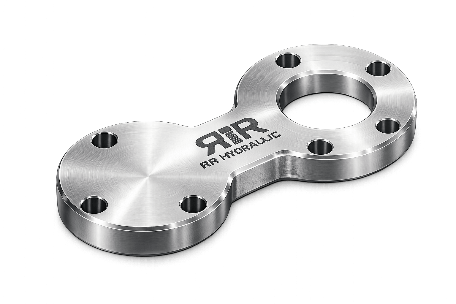
Spectacle Blind Design Principle,
Types & Process Safety Function
ASME B16.48 · B31.3 · Process Isolation · Positive Isolation
Definition and Process Safety Function
A spectacle blind (also called a figure-8 blind or spectacle plate) is a flat plate device inserted between pipe flanges to provide positive isolation of a section of piping or equipment from the remainder of the process system. Unlike a valve, which can leak internally due to seat deterioration, a properly installed spectacle blind provides a physical barrier that completely blocks the flow of process fluid — providing a level of isolation assurance that no valve can match.
The spectacle blind gets its name from its characteristic figure-8 shape, which consists of two circular discs connected by a bar: a solid blind disc (which blocks flow when rotated into the active position) and an open spacer disc or ring (which allows flow when the blind disc is rotated out). Both discs have the same outside diameter and bolt hole pattern as the mating flanges, so only one half of the spectacle is ever between the flange faces — the other half hangs outside the flanges. A handle or tab on the spectacle allows identification of which position is active from outside the flange, even with insulation covering.
Under OSHA PSM (Process Safety Management) regulations, API 570 (Piping Inspection Code) and IEC 61511 (Functional Safety), maintenance work on process equipment in hydrocarbon, toxic or hazardous service requires positive isolation before personnel entry or hot work can proceed. A closed valve — even a double-block-and-bleed arrangement — does not constitute positive isolation because valves can leak. A spectacle blind or blind flange inserted between pipe flanges provides positive isolation that physically prevents any fluid from reaching the isolated section. The spectacle blind is the preferred positive isolation device for temporary isolation during maintenance and turnarounds because the figure-8 shape means the spacer remains physically attached to the blind, reducing the risk of the wrong disc being installed or a disc being lost during turnaround operations.
Spectacle Blind Anatomy
Spectacle Blind vs Paddle Blind vs Open Spacer — Engineering Comparison
Types of Spectacle Blind Configurations
Blind Disc Thickness Design,
ASME B16.48 Dimensions & Standards
Class 150–2500 · NPS ½"–24" · Face-to-Face Dimension
Blind Disc Thickness Design — ASME B31.3 Appendix M
The minimum required thickness of a spectacle blind disc is governed by ASME B31.3 Appendix M (mandatory for process piping) and ASME B16.48 (the standard for pipeline flanges and spectacle blinds). The blind disc behaves as a uniformly loaded circular flat plate fixed at the bolt circle — the pressure load on the full bore area of the blind creates a bending stress in the disc that must be limited to the allowable stress for the blind material at operating temperature.
The ASME B16.48 standard pre-calculates and tabulates the required blind disc thickness for each NPS and pressure class combination, eliminating the need for individual calculation in most standard applications. For non-standard materials, elevated temperatures beyond the standard table range, or corrosion allowance additions, the calculation per ASME B31.3 Appendix M must be performed by the piping engineer.
t = t_min + CA // Add corrosion allowance (CA) per design specification [mm]
// WORKED EXAMPLE: NPS 6" Class 300, A516 Gr.70, design P=50 bar=5.0 MPa, bore d=168mm, S_E=138MPa
t_min = 168 × √(3×5.0/(16×138)) = 168 × √(0.00679) = 168 × 0.0824 = 13.8 mm
// Add CA=3mm → t = 16.8mm; specify 18mm nominal plate (next standard plate thickness above)
| NPS | Cl.150 Thick. (mm) | Cl.300 Thick. (mm) | Cl.600 Thick. (mm) | Cl.900 Thick. (mm) | OD — Cl.150 (mm) | OD — Cl.300 (mm) |
|---|---|---|---|---|---|---|
| 1" | 9.5 | 9.5 | 11.1 | 14.2 | 108.0 | 123.8 |
| 2" | 9.5 | 9.5 | 14.2 | 19.1 | 152.4 | 165.1 |
| 3" | 9.5 | 11.1 | 17.5 | 23.8 | 190.5 | 209.6 |
| 4" | 9.5 | 12.7 | 20.6 | 28.4 | 228.6 | 254.0 |
| 6" | 11.1 | 15.9 | 25.4 | 38.1 | 279.4 | 317.5 |
| 8" | 12.7 | 19.1 | 31.8 | 47.6 | 342.9 | 381.0 |
| 10" | 14.2 | 22.2 | 38.1 | 57.2 | 406.4 | 444.5 |
| 12" | 15.9 | 25.4 | 44.4 | 66.7 | 482.6 | 520.7 |
ASME B16.48-2020. Thicknesses are for the standard material group (ASTM A516 Gr.70 / A36 equivalent) at ambient temperature without corrosion allowance. For stainless steel (lower allowable stress at elevated temperature), thicknesses may need to be increased — verify using the B31.3 Appendix M formula with the applicable S_E for the alloy at design temperature. OD shown is the blind disc outside diameter = same as the mating flange OD. Spectacle blind weight increases rapidly with size and pressure class — NPS 12" Class 600 spectacle blind in A516 Gr.70 weighs approximately 75–90 kg; consider paddle blind for NPS 12"+ Class 600+.
The combined weight of a one-piece figure-8 spectacle blind increases rapidly with bore size and pressure class — a function of the square of the bore times the thickness. An NPS 12" Class 600 spectacle blind in A516 Gr.70 can weigh 75–90 kg. Above approximately NPS 10" Class 300 or NPS 6" Class 900 and above, consider using separate paddle blind and open spacer instead of a one-piece spectacle, to allow the two components to be individually lifted and installed. For any spectacle or paddle blind above 25 kg, a mechanical lifting device (chain block, davit arm or crane) and a designated rigging point on the blind tab must be specified in the installation procedure. Falls of spectacle blinds during installation are a serious safety hazard.
Material Grades, NACE Compliance
& Corrosion Allowance
NACE MR0175 · CA · Charpy Impact · PMI
| Material | ASTM Grade | Yield (MPa) | Allowable Stress S_E (MPa) | Temp Range (°C) | Application |
|---|---|---|---|---|---|
| CS — A516 Gr.70 | ASTM A516 Gr.70 | ≥260 | 138 | −29 to +343 | Standard process piping; general service; most common |
| CS — A516 Gr.60 | ASTM A516 Gr.60 | ≥220 | 118 | −29 to +343 | Lower strength; Class 150/300 light service |
| CS — A36 | ASTM A36 | ≥248 | 124 | −29 to +343 | Utility and non-critical service; lower cost |
| LTCS — A516 Gr.70 + Impact | ASTM A516 Gr.70 | ≥260 | 138 | −46 to +343 | Cryogenic / low-temp; Charpy impact tested at MDMT |
| SS 304 / 304L | ASTM A240 Gr.304/304L | ≥170 | 115 | −196 to +816 | Chemical, pharmaceutical, food, cryogenic service |
| SS 316 / 316L | ASTM A240 Gr.316/316L | ≥170 | 115 | −196 to +816 | Offshore, chloride, chemical, marine, pharmaceutical |
| SS 321 | ASTM A240 Gr.321 | ≥170 | 115 | −196 to +816 | High temperature, sensitisation resistance |
| Duplex 2205 | ASTM A240 S31803 | ≥448 | 172 | −50 to +315 | Offshore sour service, seawater, chloride, high strength |
| Super Duplex | ASTM A240 S32750 | ≥550 | 207 | −50 to +300 | Severe offshore, subsea, high-chloride, HPHT |
| Alloy Cr-Mo | ASTM A387 Gr.11/22 | ≥207 | 138 | −29 to +593 | High-temperature hydrogen service, refinery |
| Inconel 625 | ASTM B443 N06625 | ≥276 | 207 | −196 to +980 | Corrosive acid, high-temp, offshore, subsea |
| Titanium Grade 2 | ASTM B265 Gr.2 | ≥275 | 97 | −196 to +315 | Seawater, wet chlorine, halide service |
NACE MR0175 Compliance and HIC Requirements
Spectacle blinds in sour H≶S service must comply with NACE MR0175 / ISO 15156. For carbon steel A516 Gr.70 blinds, NACE limits the maximum hardness to 22 HRC (237 HB) throughout the plate cross-section. Standard A516 Gr.70 plate is normalised and typically complies — but every heat of plate must be hardness-verified on the cross-section and reported in the MTC. For high partial pressure H≶S service (H≶S partial pressure above 0.0003 MPa in wet gas systems), HIC (Hydrogen Induced Cracking) resistance may be required — the plate must be to NACE TM0284 HIC-tested plate (A516 Gr.70 HIC or equivalent) with acceptance criteria per NACE TM0284. For duplex 2205 blinds in sour service, ferrite content and hardness must comply with NACE and the duplex-specific requirements of ISO 15156-3.
The minimum blind thickness calculated per ASME B31.3 Appendix M is a structural minimum without corrosion allowance. The design corrosion allowance (CA) must be added to the structural minimum before specifying the blank disc thickness. CA for spectacle blinds depends on the fluid service: 0 mm for stainless steel and non-corroding alloys; 1.5 mm for mildly corrosive carbon steel service (clean hydrocarbons, utilities); 3.0 mm for moderately corrosive (wet gas, sour service); 6.0 mm for severely corrosive service. The nominal specified thickness must be the next standard plate thickness above t_min + CA.
Installation Practices, Applications
& Quality Control and Documentation
Petrochemical · Offshore · Refinery · LNG · Chemical Plant
Installation and Blind Management Practices
Every spectacle blind and paddle blind in a process plant must be registered in a blind register — a controlled document listing the blind location (equipment/line tag number, flange number), blind OD and thickness, material, pressure class, last installation date, and current status (installed/removed, blind/open). The blind register is a safety-critical document — it ensures that every installed blind is tracked and no blinds are inadvertently left installed after maintenance is complete, which could prevent start-up or cause overpressure of an isolated section. Each blind must be individually tagged with a metal tag showing its blind register number and service status ("BLIND IN" or "OPEN").
Before installation: (1) Depressurise and drain the piping section to atmospheric pressure and confirm zero pressure at the blind location using a calibrated pressure gauge; (2) Confirm the correct blind for the flange by checking OD, thickness, pressure class and material against the blind register — never install a blind without checking these parameters; (3) Inspect both gaskets that will seat against the blind disc faces — both must be new and undamaged; (4) Check the blind disc faces are undamaged, clean and free of corrosion, burrs or weld spatter that could prevent correct gasket seating. During installation: the blind disc must be centred in the flange space — check that the pipe bores are aligned and that the blind handle tab is in the correct position before beginning bolt-up. Always use a torque wrench and tighten bolts in a cross-bolt pattern to the specified torque for the flange class and gasket type.
Where a spectacle blind is equipped with a vent port, the vent protocol is: (1) Before removing the blind from the isolating position, open the vent valve and confirm zero pressure — if any pressure or fluid appears at the vent, the blind is successfully sealing and must not be removed until the upstream section is properly isolated and depressurised; (2) If no pressure appears at the vent after a reasonable time, the blind may be removed following the approved PTW (Permit to Work) procedure. The vent port confirmation step is mandatory for any toxic, flammable or high-pressure service before blind removal.
Applications by Industry
Process plant turnarounds in refineries and petrochemical plants require the systematic installation of hundreds to thousands of spectacle blinds to positively isolate every vessel, column, heat exchanger, reactor and pump before personnel entry or hot work can be authorised. The blind register is issued to the turnaround team as part of the PTW package, and blind status is tracked throughout the turnaround to ensure all blinds are reinstated to their correct service position before recommissioning. Carbon steel A516 Gr.70 is the standard material for the majority of refinery process piping blinds; NACE-compliant A516 Gr.70 HIC for sour service; A240 SS 316L for corrosive chemical service.
Offshore platforms use spectacle blinds in hydrocarbon process piping, gas lift systems, chemical injection lines and utility piping for platform maintenance, shut-down and equipment change-out. Offshore spectacle blinds are predominantly duplex 2205 (A240 S31803) for sour service and seawater-exposed piping, or SS 316L for chemical injection and general corrosive service. All offshore blinds require EN 10204 3.2 MTC with TPI countersignature, PMI, NACE hardness survey, Charpy impact testing (LTCS grades) and ferrite content measurement (duplex grades).
LNG liquefaction plants, LNG terminals and ethylene plants use spectacle blinds in A240 SS 304L (cryogenic service) or impact-tested A516 Gr.70 (for non-SS piping) for isolation of cryogenic piping sections during maintenance. The Charpy impact test at the minimum design metal temperature (MDMT) is mandatory for all carbon steel blinds in cryogenic service — minimum 27 J (20 ft-lb) at the test temperature. All dimensions and impact test results reported in the EN 10204 3.1 or 3.2 MTC.
Chemical plants use A240 SS 316L spectacle blinds for isolation of corrosive process lines (acid, alkali, solvent service) during equipment maintenance and cleaning. Pharmaceutical plants specify electro-polished SS 316L blinds (Ra ≤ 0.8 µm) for product contact piping isolation. For highly corrosive chemical service, Inconel 625, Hastelloy C276 or titanium Grade 2 blinds are specified where carbon or stainless steel would be unsuitable for the process chemistry.
Quality Control and Inspection
Spectacle blind QC covers: (1) Dimensional inspection — OD, bore (open ring), thickness (uniform across the disc — any taper indicates undersize machining or rolling), handle/tab size and position; (2) Flatness verification — the blind disc faces must be flat within 0.8 mm per metre of disc diameter to ensure uniform gasket seating; a dished or warped blind will not seal reliably; (3) Surface finish — blind disc seating faces at 125–250 AARH for spiral-wound gaskets or 63 AARH smooth for full-face PTFE gaskets; (4) Material identity — PMI on all alloy blinds (SS, duplex, Inconel, titanium); (5) NACE hardness — hardness verification on the cross-section for sour service carbon steel blinds; (6) Charpy impact — for LTCS and impact-tested grades.
Export Packaging and Preservation
- Spectacle blinds wrapped individually in VCI polyethylene film for carbon steel; SS, duplex and alloy blinds in clean poly bags (segregated from CS)
- Blind disc faces protected with foam face pads or plywood covers retained by strapping to prevent surface damage during transport
- Blinds stored flat or standing on edge with face protection — never stack blinds face-to-face without protective spacers as the serrated face finish will damage both faces
- Each blind tagged with: NPS, pressure class, material, thickness, heat/lot number and PO number — metal tag wired to the handle tab
- MTC (EN 10204 3.1 or 3.2), dimensional inspection report (OD, bore, thickness, flatness), surface finish report, PMI (alloy grades), hardness report (NACE), Charpy impact report, ferrite content (duplex), in waterproof sealed envelope with each consignment
- Large-bore blinds (above approx. 25 kg) packed with designated lifting point marked and rigging instructions included in the package
| # | Document | Standard / Reference | Minimum Requirement |
|---|---|---|---|
| 01 | Material Test Certificate (MTC) | EN 10204 3.1 / 3.2 | 3.2 (TPI co-signed) for offshore / NACE / duplex / safety-critical |
| 02 | Dimensional Inspection Report | ASME B16.48 / project drawing | OD, bore, thickness (5 points min), handle dimensions — all mandatory |
| 03 | Flatness Verification Report | Project specification | ≤0.8 mm/m across blind disc face — both sealing faces |
| 04 | Surface Finish Report (AARH) | ASME B46.1 | 125–250 AARH for SWG service; 63 AARH smooth for full-face PTFE |
| 05 | PMI Report (XRF / OES) | Project specification | 100% SS, duplex, Inconel, Monel, Ti and all alloy blinds |
| 06 | Hardness Test Report (HB / HRC) | ASTM E10 / NACE MR0175 | NACE sour service: ≤22 HRC cross-section; duplex: ≤28 HRC |
| 07 | HIC Test Report | NACE TM0284 | Required for NACE HIC-resistant plate (sour high H≶S partial pressure service) |
| 08 | Charpy Impact Test Report | ASTM A370 / EN ISO 148 | Mandatory for LTCS impact-tested grades; ≥27 J at MDMT |
| 09 | Ferrite Content Report (Duplex) | ASTM E562 / image analysis | Mandatory for duplex 2205 and super duplex; FN 35–65% |
| 10 | ISO 9001 Manufacturer Certificate | ISO 9001:2015 | Current; scope must include pressure vessel / piping plate fabrication |
| 11 | ISPM-15 Phytosanitary Certificate | IPPC / FAO | All wood packing for international export |
RR Hydraulics manufactures and exports spectacle blinds and paddle blinds in all configurations (standard figure-8, RTJ, split large-bore, drilled/tapped vent) per ASME B16.48, in A516 Gr.70 / Gr.60, impact-tested LTCS, A240 SS 304L and SS 316L, duplex 2205 and super duplex S32750, Cr-Mo alloy A387, Inconel 625, Monel 400, Hastelloy C276 and Titanium Grade 2. NPS ½"–24", Class 150–2500, RF/FF/RTJ face types. EN 10204 3.1/3.2 MTC, flatness and AARH reports, PMI, NACE hardness, HIC testing, Charpy impact, ferrite content (duplex), TPI witness by BV/DNV/Lloyds/SGS/TÜV. 48-hour express dispatch on standard sizes.